

Cutting gears that actually mesh
Difficulty: medium. Time: 15 minutes design, 45 minutes making. Best methods: laser-cut plywood or acrylic, 3D printed gears.
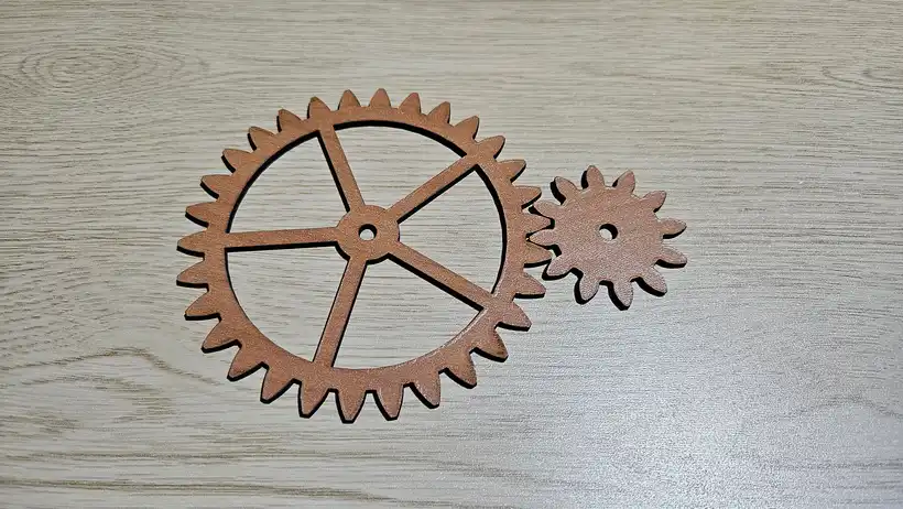
Two gears mesh when they share a Module and a Pressure angle. Nothing else has to match, which is why a 12 tooth pinion drives a 40 tooth wheel happily as long as both were cut with the same two numbers.
The 3D tab shows the whole arrangement assembled and turning at its true ratio, with each level at its real height. Press play, watch it mesh, and fix anything that looks wrong there before you cut it in wood.
What You'll Need
- Laser cutting: 3 to 6 mm plywood or acrylic. Acrylic runs quieter and wears better than ply.
- 3D printing: PLA or PETG. PETG teeth survive load better.
- Hardware: 3 mm or 6 mm dowel or bolts for the arbors, plus washers so the gears do not rub on the base
- For compound stacks: wood glue and a flat surface, so the two levels set square to each other
Step 1 - Choose the arrangement
- Meshing pair and Gear train are the everyday starting points. A train runs from three to twelve gears, and the layout angle turns each step a little further than the last, so zero gives a straight chain and larger values curl it into an arc.
- In a train, Tooth pattern decides the sizes: Alternating swaps between your two tooth counts, Tapered ramps from the first down to the second across the chain, and All the same keeps one size throughout.
- Planetary set gives a big reduction in a small circle. The generator checks that the ring has sun plus twice the planet teeth, and that the planets can sit evenly.
- Ring and pinion is an internal gear, which turns the pinion in the same direction rather than reversing it.
- Rack and pinion turns rotation into a straight slide.
- Compound stack puts a big wheel and a small pinion on one arbor in two layers, which is how you get a large reduction without a huge gear.
- Non-circular pair rolls an ellipse, a lobed flower, an eccentric or a rounded square against its true conjugate. The speed swings as it turns.
Step 2 - Size the teeth
Module is tooth size in millimetres: pitch diameter is module times teeth. Module 3 to 5 is the sweet spot for laser-cut gears, because module 1 or 2 teeth are smaller than the kerf can hold. Number of teeth then sets the diameter. Stay at 17 teeth or more at a 20 degree pressure angle to avoid undercut, or add profile shift to go lower.
Profile shift fattens the tooth root and is the proper fix for a small pinion. A shift of 0.3 to 0.5 lets you run down to 8 or 10 teeth. Switching the profile to Cycloidal does the same job a different way, and is what clockmakers use to get pinions down to six leaves.
Step 3 - Set the fit
- Backlash is the play between meshing teeth, taken off the tooth thickness. Start at 0.1 to 0.2 mm for laser cutting, which is roughly one kerf, and more if your material chars.
- Root clearance is how far the root is cut below the pitch line, given as a fraction of the module. The standard 0.25 is a good default.
- Root fillet rounds the corner where the flank meets the root. A fillet is what stops a gear splitting along the grain under load, so leave some in for plywood.
Step 4 - Style the centres
Centre style cuts the web between the hub and the rim. Spokes and Cross are structural, Lightening holes are the classic mechanical look, and Filigree and Fine web are for wall art. On a non-circular gear the cutouts follow the pitch curve, so they get slimmer where the gear pinches in. If a gear is too small for the pattern you picked, the generator leaves it solid rather than cutting something too thin to survive.
Step 5 - Export the cut sheet
The Assembled layout overlaps parts, because that is where they actually sit. Switch to Cut sheet before exporting and the parts are packed side by side with a gap so nothing is cut twice. Leave Add a setting gauge on and the sheet gains a small strip with two holes at the exact centre distance, which beats measuring: clamp it to your base plate and mark through it.
Choose Your Build Method
Cut settings
- Cut gears with the tightest focus you have. Every bit of kerf comes off the tooth flank, which is why backlash is a setting here.
- Cut one gear and one pinion as a test, mount them at the reported centre distance, and turn them by hand before cutting a whole train.
- Acrylic gears can be cut two at a time and glued face to face for a wider, stronger tooth.
- Cut the setting gauge with the rest of the sheet and use it as a drilling template: drop it on the base plate, mark through both holes, and your shafts are at the exact centre distance.
Building a compound stack
A compound stage is a wheel and a pinion on the same arbor, at two different heights. Cut both, plus the spacer rings, and thread them onto a dowel in the order wheel, spacer, pinion. The spacers have an oversized bore on purpose, so they set the gap without gripping the shaft. The 3D tab shows the levels at their real heights, so you can see which wheel meshes with which before you glue anything. Let the glue set with the stack flat on the bench so the two levels stay parallel.
Non-circular pairs
The mate is solved from the no-slip condition, so the pair really does roll without skipping. Both axles are fixed at the reported centre distance, and the ratio swings as they turn. If the tool warns that the curve is too pinched, either drop the eccentricity or drop the module until the teeth fit around the tight end.
Make It Yours
- Cut the Steampunk wall art preset in three colours of acrylic and stack the wheels behind a face plate as a kinetic panel.
- Cut an elliptical pair and mount them behind a window so people can watch the speed swing.
- Add lightening holes to the big wheel and leave the pinion solid for a mechanical look.
- Run a planetary set as a bottle opener or a fidget: sun in, ring fixed, carrier out.
- For a planetary display clock with exposed cog wheels that turn around a ring gear, move over to the Moving Gear Wall Clock generator.
Keep up with MyLaserTools.
Email me about new tools, product updates, tutorials, and occasional MyLaserTools offers. Unsubscribe at any time.
© 2026 MyLaserTools.com. All rights reserved.